
 English
 Español
 Portugues
 Pусский
 Français
 Deutsch
 日本語
日本語 한국어
한국어 العربية
 Italiano
 Nederlands
 Polski
 ไทย
ไทย Türk dili
 Indonesia
 Tiếng Việt
 čeština
 Română
 Suomalainen

When I work with terminal connector equipment, I pay close attention to the small mechanical parts that control movement. A machine may have a powerful motor and a modern control system, but if the mechanical motion is not accurate, the whole production process can still become unstable. This is one reason I focus on Precision Cam Components, including the Custom Conjugate Camshaft for Terminal Connector Equipment.
At Dongguan Jifan Precision Machinery Co., Ltd., I manufacture custom cams, conjugate cams, Cam Mechanisms, eccentric shafts, crankshafts, plate cams, and other precision mechanical parts. We work from customer drawings, specifications, samples, and equipment requirements. For a terminal connector machine, the Camshaft is not simply a rotating metal shaft. It is part of the motion system that can determine when a component feeds, moves, returns, clamps, inserts, or releases.
I also understand that every machine is a little different. One terminal processing machine may need a short movement with a fast return, while another may need a longer feed stroke and a controlled dwell. That is why I do not recommend choosing a standard camshaft simply because the outside dimensions look similar. The cam profile, timing, shaft geometry, follower arrangement, and installation dimensions all need to work together.
In this article, I will explain how I approach a custom conjugate camshaft for terminal connector equipment, how the mechanism works, what I look at during machining, where this type of component can be used, and what customers should consider before ordering.
1. What Is a Conjugate Camshaft for Terminal Connector Equipment?
I usually explain a conjugate cam in simple terms. A normal cam uses its profile to push a follower through a planned movement. A conjugate cam system uses two matching cam profiles to control the follower in both directions. The two cams normally work together on the same shaft, while their followers are connected to the same moving member.
This arrangement creates what engineers call positive motion or positive drive. Instead of relying only on gravity or a spring to bring the follower back into contact with the cam, the complementary cam profile can control the return movement as well.
Carnegie Mellon University's introduction to mechanisms explains that a cam mechanism can transform rotary motion into translating or oscillating motion. It also describes a dual or conjugate cam arrangement in which two cam surfaces work with two rollers mounted on the same follower.
In practical terms, I see the conjugate camshaft as a motion-control component. The motor provides rotation. The camshaft carries the designed profiles. The follower follows those profiles. The follower then produces the required machine movement.
For terminal connector equipment, this movement may be related to feeding terminals, moving a tooling component, positioning a connector, returning a mechanism, or coordinating another part of the production cycle. The exact function depends on the machine design.
This is important because I do not assume that every terminal connector machine uses the same cam mechanism. The customer's actual equipment drawing tells us much more than the product name alone.
Why Use a Conjugate Cam?
One useful feature of a conjugate cam mechanism is that the follower can be mechanically controlled during both the forward and return portions of its movement. This can be helpful when the machine needs a defined motion path instead of simply pushing the follower one way and allowing a spring to bring it back.
Technical references describe conjugate cams as positive-drive arrangements in which complementary cam profiles work with follower rollers to maintain mechanical constraint.
For a production machine that repeats the same movement many times, this type of controlled motion can be useful. It allows the machine designer to build the required movement into the cam profile instead of leaving the return movement mainly to a spring.
| Cam Arrangement | How the Follower Is Controlled | Typical Motion Control Characteristic | Possible Use in Automated Equipment |
|---|---|---|---|
| Single Cam with Spring Return | Cam drives one direction; spring assists return | Simple mechanical arrangement | General automated mechanisms |
| Groove Cam | Follower roller is constrained by a cam groove | Positive mechanical constraint | Feed, transfer, indexing and other controlled movements |
| Conjugate Cam | Two complementary cam profiles control two followers | Positive control in both movement directions | High-control motion systems and automated machinery |
Source: Carnegie Mellon University, Introduction to Mechanisms – Cams; Sankyo cam terminology reference.
2. How the Custom Conjugate Camshaft Works in Terminal Connector Equipment
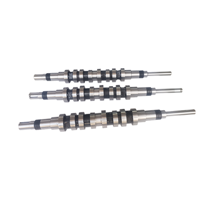
When I look at a custom camshaft project, I start with the motion rather than the metal. Before machining anything, I want to understand what the machine needs the shaft to do.
A simplified terminal connector machine may have several repeated actions. A terminal can be fed into position, a mechanism can move forward, another component can hold or process it, and the tooling can then return to its starting position. In a cam-driven system, these actions can be linked to the rotation angle of the camshaft.
Think of the camshaft as the machine's mechanical timetable. As the shaft turns, the cam profile tells the follower where it should be. One section of the profile may create a rise. Another may create a dwell. Another may create a return. The machine designer decides the desired motion, and the cam geometry is then developed around that motion.
In a conjugate arrangement, the second cam profile works with the first profile. The two profiles are designed as a pair. They are not simply two random cams mounted beside each other.
This relationship is one of the most important points in manufacturing. If the profiles, center distance, angular phase, or follower positions are not correct, the complete mechanism may not move as intended.
A Simple Motion Example
Suppose a terminal feeding mechanism needs to move forward, pause briefly, and then return. The machine designer can define this movement as a motion curve. The cam profile is then created to produce that curve as the camshaft rotates.
The first cam can provide the driving movement while the conjugate cam controls the opposite side of the follower arrangement. The result is a mechanically constrained movement rather than a simple push-and-spring-return action.
Research published in Mechanism and Machine Theory describes conjugate cam use in cam-type transfer systems and notes that complementary cam arrangements can remove the need for redundant preload while helping prevent follower separation.
I do not use that research as a promise about the performance of every terminal connector machine. Actual results depend on the complete mechanism, speed, load, lubrication, bearing condition, assembly accuracy, and many other factors. Instead, I use the engineering principle as a guide when discussing the role of conjugate cam components with customers.
Connection With Terminal Feeding
Terminal feeding is a good example of why accurate motion matters. A terminal needs to arrive at the correct position before the next machine action takes place. If the feed movement is inconsistent, the next operation may not line up correctly.
A U.S. patent describing a terminal feeding device for termination machines specifically discusses the relationship between cam and linkage mechanisms, terminal feeding, feed position, and crimping performance.
This does not mean every terminal connector machine uses the same design. It simply shows why the mechanical timing of feeding equipment is an important engineering consideration.
3. Main Features of Our Custom Conjugate Camshaft
When I describe our Custom Conjugate Camshaft for Terminal Connector Equipment, I prefer to focus on practical features instead of making broad claims. The part should be designed around the machine and manufactured according to the agreed technical requirements.
Custom Cam Profile
The cam profile is the heart of the mechanism. We can manufacture customized cam profiles based on customer drawings, motion requirements, and equipment specifications. The exact profile depends on the required displacement, speed, acceleration, dwell, return movement, and other design factors.
Integrated Camshaft Structure
A conjugate camshaft may carry two or more related cam profiles on one shaft. The shaft geometry, cam position, and phase relationship need to match the customer's mechanism.
Precision Dimensional Control
Shaft diameter, shoulder location, mounting position, hole geometry, keyway location, and other features can all matter during assembly. We machine and inspect these features according to the agreed drawing and specifications.
Customized for Machine Space
Automated equipment often has limited internal space. A custom shaft allows the designer to work with the actual machine layout rather than trying to force a standard component into an unsuitable position.
Suitable for Repeated Motion
Terminal connector equipment is normally designed around repeated machine cycles. The camshaft therefore needs to be manufactured consistently so that the motion profile can be reproduced from cycle to cycle under the machine's specified operating conditions.
Inspection Before Delivery
After machining, we carry out dimensional inspection, quality checking, and final verification according to the agreed specifications. Inspection requirements vary from one project to another, so I prefer to define the critical inspection points during the quotation and technical review stage.
| Feature | Why It Matters | Typical Review Method |
|---|---|---|
| Cam Profile | Controls the intended follower movement | Drawing and profile requirements |
| Cam Phase | Coordinates related machine movements | Drawing and assembly requirements |
| Shaft Diameter | Matches bearings, couplings or other mating parts | Dimensional inspection |
| Center Distance | Maintains the required relationship between mating components | Drawing-based inspection |
| Mounting Features | Allows correct installation in the machine | Dimensional and visual inspection |
| Surface Finish | Can influence contact and friction at specified surfaces | According to customer specification |
Source: The feature relationships above reflect standard cam-mechanism design considerations. Carnegie Mellon University's cam reference describes cam profiles as the means of converting rotary motion into follower movement, while engineering references identify profile accuracy and follower constraint as important design considerations.
4. From Cam Design to Precision Machining: How I Make the Part
A custom camshaft project normally starts with technical information. The more complete the information, the easier it is to plan the machining process correctly.
Step 1: I Review the Drawing
I first look at the drawing or 3D model. I check the overall shaft dimensions, cam locations, critical diameters, mounting features, material, tolerance requirements, and surface requirements.
If the customer has a sample rather than a finished drawing, I need to understand which dimensions are critical and which dimensions can be adjusted. This distinction can make a big difference during manufacturing.
Step 2: I Understand the Motion
For a normal shaft, dimensions may be the main focus. For a camshaft, motion is equally important. I want to know what the follower needs to do and how the camshaft fits into the machine cycle.
If the customer already has a complete cam profile, we manufacture according to that information. If the project requires cam design support, we can discuss the required movement and mechanical structure before finalizing the machining data.
Step 3: I Plan the Machining Process
Depending on the structure, the process may include CNC turning, milling, drilling, grinding, profile machining, and other operations. The exact process depends on the part geometry and required accuracy.
The order of machining operations matters. A reference surface created early in the process may be used to locate another feature later. If the sequence is poorly planned, errors can accumulate.
Step 4: Cam Profile Machining and Grinding
Cam profiles can contain curves that are more complicated than normal circular surfaces. For this reason, profile machining and grinding require careful process control.
Our manufacturing capability includes irregular cam grinding and Profile Grinding. These processes are especially useful for customers who need non-standard cam shapes rather than simple round components.
Step 5: Dimensional Inspection
After machining, we inspect the finished component according to the agreed requirements. Depending on the drawing, this can include shaft dimensions, cam position, profile-related requirements, hole positions, and other critical features.
Step 6: Final Verification
Before delivery, I want the production team to make one final check against the order requirements. This is a simple step, but it helps prevent avoidable problems such as incorrect quantity, wrong configuration, or packaging issues.
Step 7: Protective Packaging
Precision mechanical components should be protected during transportation. We use standard protective packaging to reduce the risk of damage during handling and shipping. If a customer has special packaging requirements, customized packaging can be arranged according to the project.
| Production Stage | Main Activity | Purpose |
|---|---|---|
| Technical Review | Drawing, material, dimensions, motion requirements | Confirm the manufacturing requirements |
| Process Planning | Machining sequence and reference setup | Build a practical production route |
| CNC Machining | Turning, milling, drilling and related operations | Create the shaft and mechanical features |
| Profile Machining / Grinding | Manufacture the specified cam profile | Achieve the required cam geometry |
| Inspection | Dimensional and quality checks | Verify compliance with agreed specifications |
| Final Verification | Order and product review | Prepare the finished component for shipment |
Source: Manufacturing workflow is based on Dongguan Jifan Precision Machinery Co., Ltd.'s stated custom machining, dimensional inspection, quality checking, and final verification practices. The technical importance of cam-profile accuracy is also discussed in engineering cam-design references.
5. Why Precision Matters in Terminal Connector Machinery
A terminal connector machine is made up of many moving parts. The terminal feeder, tooling, guides, holders, sensors, drive system, and mechanical transmission all need to work together. If one part is slightly out of position, the problem may show up somewhere else in the machine.
This is why I pay particular attention to the relationship between cam profile and shaft geometry. A cam profile can be accurate by itself, but if its angular position on the shaft is incorrect, the machine timing can still be wrong.
The same applies to the relationship between two conjugate cams. They need to work as a matched pair. Their phase, geometry, and installation relationship are part of the overall motion system.
Controlled Feeding
Terminal feeding often needs a repeatable stroke. The mechanism has to move the terminal or strip into the correct position before the next operation. A cam-based feed mechanism can use a defined profile to create this movement.
Coordinated Machine Timing
One camshaft can control several related movements through different cam profiles. This can help synchronize operations mechanically, depending on the equipment design.
Reduced Dependence on Simple Spring Return
A conjugate cam arrangement can mechanically control both sides of a follower movement. Technical literature describes this as a positive-drive or form-closed mechanism.
Better Fit for Customized Equipment
Terminal connector equipment is often designed around a particular terminal size, tooling arrangement, production process, or automation layout. A custom camshaft allows the mechanical motion component to follow that equipment design.
I would not promise that a custom cam automatically makes a machine faster. Machine speed depends on the complete system, including motor power, inertia, load, cam profile, follower design, lubrication, bearings, control system, and structural stiffness. What customization gives us is the ability to manufacture the mechanical component around the required design.
| Factor | Potential Effect on the Mechanism | What I Check During Manufacturing |
|---|---|---|
| Cam Profile | Influences follower displacement and motion curve | Profile requirements and machining accuracy |
| Cam Phase | Influences timing between different machine actions | Angular position and assembly references |
| Follower Alignment | Influences contact and movement | Matching dimensions and installation requirements |
| Shaft Geometry | Influences mounting and rotation | Diameters, shoulders, holes and key features |
| Surface Condition | Can affect contact and wear behavior | Specified surface requirements |
Source: Carnegie Mellon University, cam mechanism fundamentals; ScienceDirect research on conjugate cam design and motion requirements.
6. Applications of Custom Conjugate Camshafts Beyond Terminal Connector Equipment
Although this product is designed around terminal connector equipment, the manufacturing principle is useful in many other automated machines. Wherever a machine needs a carefully timed mechanical movement, a custom camshaft may be worth considering.
Terminal Crimping and Connector Assembly Equipment
This is the most direct application. Terminal processing equipment may use cams to coordinate feeding, positioning, return, cutting, clamping, or other repeated mechanical actions.
Some commercial crimping machine designs list feed cams and shafts among their tooling components, showing the practical role of cam-based mechanisms in terminal processing equipment.
Wire and Cable Processing Machinery
Wire processing machines often contain repeated feeding and positioning movements. Custom cams can be designed to match the required stroke and timing.
Electronics Assembly Equipment
Electronics production equipment frequently requires compact motion mechanisms. A custom camshaft can be useful when several movements need to be mechanically coordinated within limited space.
Packaging Machinery
Packaging equipment often contains feeding, cutting, pressing, folding, or positioning mechanisms. These repetitive actions are well suited to carefully designed cam motion.
Printing Equipment
Printing machinery can require synchronized movement between multiple components. Our custom cams, cam mechanisms, and shafts can be manufactured according to specific equipment requirements.
Food and Beverage Machinery
Automated filling, packaging, feeding, and handling equipment may use custom mechanical components to produce repeated movements.
Daily Chemical and Biopharmaceutical Equipment
Automated production equipment in these industries can contain compact motion mechanisms. The specific mechanical component depends on the machine architecture and process.
Plastics and Hardware Machinery
Production equipment for plastics and hardware products can require custom shafts, cams, eccentric components, and other precision parts for automated motion.
In all of these applications, I use the same basic approach: understand the machine movement, confirm the mechanical interfaces, select a practical machining process, and inspect the finished part against the agreed requirements.
7. Why Choose Dongguan Jifan for Custom Conjugate Camshaft Machining?
I believe a good machining supplier should understand more than how to remove material from a piece of metal. For cam components, the supplier needs to understand why the profile exists and how the part fits into the machine.
Our Main Focus Is Custom Motion Components
Dongguan Jifan Precision Machinery Co., Ltd. specializes in cam mechanisms, Custom Cam Machining, cam design, profile grinding, eccentric shafts, crankshafts, plate cams, and conjugate cams. This means that our work is closely connected with motion-control components rather than general-purpose metal parts.
We Work From Customer Drawings
If you already have a finished drawing, we can manufacture the component according to the specified requirements. We can also review samples, specifications, and equipment information when the project is still being developed.
We Understand Customized Cam Geometry
A standard circular shaft is relatively simple. A camshaft with multiple profiles and specific timing relationships is different. Our experience with cam mechanisms and profile grinding allows us to work with more complicated mechanical shapes.
We Support Different Industries
Our precision components are used in daily chemical, biopharmaceutical, food processing, electronics, plastics and hardware, printing, beverage, and other automated machinery applications.
We Inspect Before Delivery
Before shipment, products undergo machining, dimensional inspection, quality checking, and final verification according to the agreed specifications. We do not use one fixed inspection list for every product because different drawings have different critical dimensions.
We Support Flexible Logistics
Depending on destination and order size, products can be shipped by express, air freight, sea freight, or another suitable transportation method. Protective packaging is used to help reduce transportation damage, while customized packaging can be discussed when needed.
We Focus on Practical Communication
For a custom camshaft, communication is part of the manufacturing process. Before production, I want to know the drawing revision, quantity, material, critical dimensions, machine application, and any special requirements. This makes the quotation and production process much clearer for both sides.
8. FAQ About Custom Conjugate Camshaft for Terminal Connector Equipment
Q1: What is a custom conjugate camshaft?
A custom conjugate camshaft is a shaft carrying complementary cam profiles designed to work together with a follower arrangement. The two profiles are designed as a matched mechanical system and can provide controlled motion in both directions. The exact structure depends on the customer's equipment design.
Q2: Can you manufacture a conjugate camshaft according to our drawing?
Yes. We manufacture custom camshafts according to customer drawings, specifications, samples, and equipment requirements. Please provide the drawing or 3D model, material, quantity, tolerance requirements, surface requirements, and other available technical information for review.
Q3: Can you make a camshaft for terminal crimping equipment?
Yes, subject to technical review. We can manufacture custom camshaft components for terminal connector equipment, crimping machinery, feeding mechanisms, and other automated production equipment when the required geometry and machining process are suitable for our capabilities.
Q4: What information do you need before quoting?
The most useful information includes a 2D drawing or 3D model, material specification, quantity, critical dimensions, tolerances, cam profile information, mounting requirements, and machine application. If the design is not complete, a sample and basic equipment information can also help us understand the project.
Q5: Can you design the conjugate cam profile?
We provide cam design and custom Machining Services. If you need design assistance, we can discuss the required motion, stroke, dwell, return movement, shaft structure, and equipment requirements. Final engineering parameters should be confirmed by the customer's equipment design team.
Q6: What machining processes can you provide?
Depending on the component structure, machining may include CNC turning, milling, drilling, profile machining, grinding, and other precision operations. We select the process according to the geometry, material, quantity, tolerance, and surface requirements.
Q7: Can you provide profile grinding for irregular cam shapes?
Yes. Irregular cam grinding and profile grinding are among our Machining Capabilities. The exact grinding method depends on the cam geometry, material, required profile, dimensional requirements, and production quantity.
Q8: How do you control the quality of the finished camshaft?
We perform dimensional inspection, quality checking, and final verification according to the agreed specifications. The critical inspection points should be identified from the customer's drawing and technical requirements before production.
Q9: How long does production take?
The production cycle depends on the camshaft complexity, material, quantity, machining requirements, and customization level. After receiving the technical information, we can evaluate the project and confirm the expected production schedule.
Q10: Can you provide small quantities?
Custom production quantities can be discussed according to the project. The appropriate production method depends on the camshaft design, complexity, machining process, and required quantity.
Q11: How do you package the camshaft for shipment?
We use protective packaging to help prevent damage during handling and transportation. For special projects, customized packaging requirements can be discussed according to the customer's shipping and storage needs.
Q12: How can I start a custom camshaft project?
Send us your drawing, 3D model, sample information, or machine requirements. I recommend including the required quantity, material, cam profile information, critical tolerances, and application details. We can then review the manufacturing requirements and discuss the next step.
Conclusion: Building the Camshaft Around the Machine
When I manufacture a Custom Conjugate Camshaft for Terminal Connector Equipment, I do not look at it as just another machined shaft. The shaft is part of a motion system. Its cam profiles, phase relationship, dimensions, and mounting features all need to work with the machine around it.
Conjugate cam mechanisms are useful when the designer needs controlled follower movement and positive mechanical constraint. For terminal connector equipment, this can be relevant to feeding, positioning, transfer, return, and other repeated operations. The actual benefit, however, depends on the complete machine design.
At Dongguan Jifan Precision Machinery Co., Ltd., I focus on custom cam machining, cam design, profile grinding, conjugate cams, eccentric shafts, crankshafts, and other precision mechanical components. We manufacture according to customer drawings, specifications, and equipment requirements, followed by dimensional inspection and final verification.
If you are developing a terminal connector machine, terminal crimping machine, wire processing system, electronics assembly machine, or other automated equipment and need a Precision Conjugate Camshaft, send us your drawing or project information. We can review the cam profile, shaft structure, machining requirements, quantity, and inspection requirements before production.
My goal is simple: understand the movement first, manufacture the mechanical part accurately, and make sure the finished component matches the requirements agreed for the project.
Need a custom conjugate camshaft manufacturer? Contact Dongguan Jifan Precision Machinery Co., Ltd. for Custom Camshaft Machining, conjugate cam manufacturing, Terminal Connector Machine Camshaft production, profile grinding, and other custom precision machining services.
Technical References
Carnegie Mellon University, Introduction to Mechanisms – Cams: fundamental explanation of cam mechanisms, follower motion, and dual/conjugate cam arrangements.
Sankyo Seisakusho, Cam Terminology: technical definitions related to positive cams, conjugate cams, pressure angle, preload, and cam mechanisms.
Mechanism and Machine Theory, Elsevier: research on cam-type transfer mechanisms and the use of conjugate cams for controlled motion.
Google Patents, US20070000124A1: technical background concerning terminal feeding devices, cam mechanisms, terminal positioning, and termination machines.
EXCON, terminal crimping machine and tooling information: example of feed cam and shaft components used in terminal crimping equipment.
